Template:Ninebot Max STLink BMS Flash Procedure
Finding the Debug points
The top of the battery is covered in gray silicon. The area around the debug pins must be removed to access the pins as shown below.
It is just below the BMS 4-pin JST data cable.
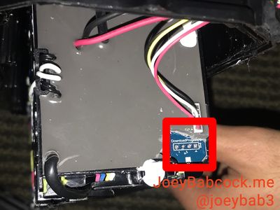
Some boards have a slightly different layout.

Once you have these pins exposed, either solder jumper cables on or hold them for the next step according to the diagram below:
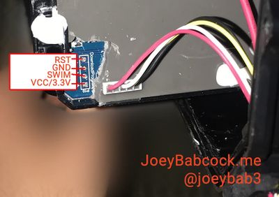
Some boards have a slightly different layout.
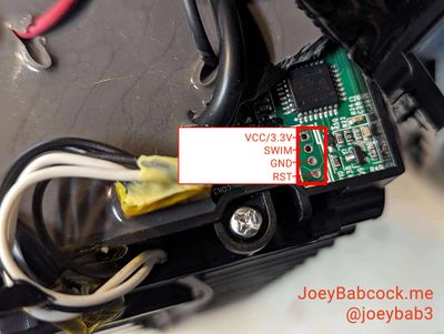
Flashing Stock BMS Firmware
The debug pins must be connected to the STLink as shown. This can be done by manually holding jumpers to the debug points or by soldering wires to connect to the jumpers.
Download the hex file from ScooterHacking, and open it in STVP.
To flash, a separate software must be used instead of the normal openOCD/STM32 STLink Utility method.
To flash it, different software is needed, in this case, STVP.
1. Connect ST-Link to BMS through STVP
2. STM8L15xK6 for the chip
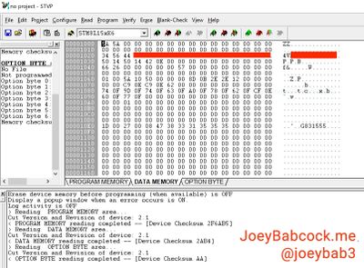
3. In the top menu select Read -> All Tabs
4. Select the bottom tab labeled "PROGRAM MEMORY"
5. Open the full dump file, you can find the full dump file here: Ninebot Max BMS 1.3.4.
6. In the top menu select Program -> All Tabs
Verify Successful Flash
Connect the White of the battery data line to TX and yellow to RX and black to ground in order to check the version. It should read 1.3.4 or 5.3.4, and not 4.4.8 or anything else.

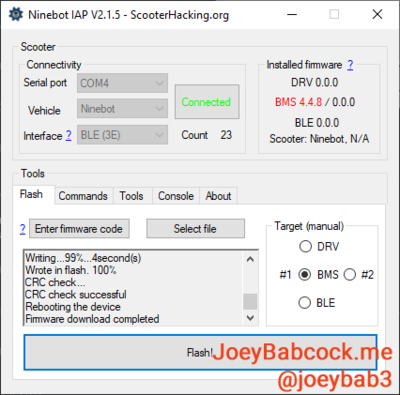
Alternatively, connect the battery to a scooter or skeleton setup and check the version there.