STLink Ninebot ESX ESC: Difference between revisions
No edit summary |
|||
| Line 66: | Line 66: | ||
==Flashing== | ==Flashing== | ||
===Connect the STLink to the Master Control Board=== | |||
Connect pins to 5v/VCC, GND, SWDIO, and SWCLK as shown below. | Connect pins to 5v/VCC, GND, SWDIO, and SWCLK as shown below. | ||
| Line 76: | Line 78: | ||
Here I did a poor solder job but it still works. | Here I did a poor solder job but it still works. | ||
===STM32 STLink Utility=== | |||
Download the [https://github.com/scooterhacking/firmware/blob/e0b55b1ef90aebf44305ab679d2494ceece0ce62/Ninebot%20ESx%20and%20SNSC1.x/DRV/esc139_fulldump.bin 1.3.9 full dump .bin from ScooterHacking]. | Download the [https://github.com/scooterhacking/firmware/blob/e0b55b1ef90aebf44305ab679d2494ceece0ce62/Ninebot%20ESx%20and%20SNSC1.x/DRV/esc139_fulldump.bin 1.3.9 full dump .bin from ScooterHacking]. | ||
| Line 83: | Line 87: | ||
Always check that you are downloading files from trusted sources(aka ScooterHacking) to avoid flashing malicious firmware. | Always check that you are downloading files from trusted sources(aka ScooterHacking) to avoid flashing malicious firmware. | ||
Open STM32 STLink Utility and | Open STM32 STLink Utility and attempt to connect to the esc with the button shown below. | ||
[[File: STM32STLinkUtilityConnect.png|thumb|center|400px|Click the button shown here to attempt to connect.]] | |||
You should be warned that readout protection is enabled if it is connected successfully. | |||
[[File: STM32STLinkUtilityReadoutProtectionWarning.png|thumb|center|400px|The warning will be fixed in the next steps.]] | |||
Next, press CTRL + B to open the chip settings. | |||
Select "Disabled" under "Read out protection". | |||
[[File: STM32STLinkUtilityChipSettings.png|thumb|center|400px|The warning will be fixed in the next steps.]] | |||
Next, click the open icon on the far right as shown. | |||
[[File:STM32STLinkUtilityOpenFile.png|thumb|center|400px|Click to open the file.]] | |||
Select the esc_fulldump139.bin file you downloaded earlier. | |||
[[File:STM32STLinkUtilityOpenFulldumpFile.png|thumb|center|400px|Click to open the esc_fulldump139.bin file you downloaded earlier.]] | |||
Click Target->Program & Verify or press CTRL + P. | |||
[[File:STM32STLinkUtilityProgramAndVerify.png|thumb|center|400px|Open the programming menu.]] | |||
Confirm one last time that the file you are flashing is the full dump and then press "Start". | |||
[[File:STM32STLinkUtilityStartProgramming139FullDump.png|thumb|center|400px|Match the settings and confirm the file before pressing start.]] | |||
The program will now program the chip with the full dump. | |||
Once it finishes check the console to make sure it was successful. | |||
[[File:STM32STLinkUtilitySuccessfulProgramming139FullDump.png|thumb|center|400px|Completely finished and successful programming.]] | |||
[[Category: Scooters]][[Category: Ninebot]][[Category: ESX]] | [[Category: Scooters]][[Category: Ninebot]][[Category: ESX]] | ||
Revision as of 19:51, 28 May 2023
In the case of a bricked ESC/Controller/Control Board, STLinking can save the master control board from needing to be replaced in some instances.
This is often the only way to save a board that has been bricked when the wrong firmware was flashed or an update failed.
Accessing the Debug Pins
Removing the Pole
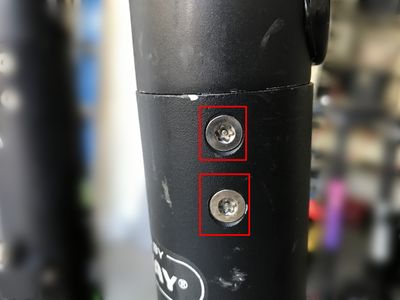
Remove the 4x Security Torx T25 screws or Hex Screws that hold the handlebar in place on the pole.
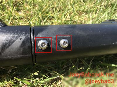
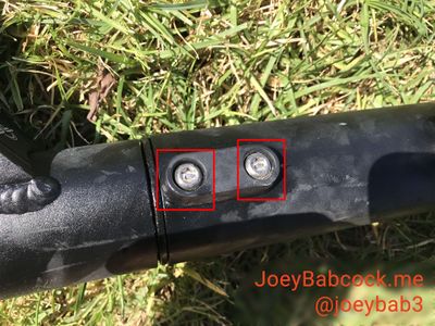
Remove the 4x Security Torx T30 screws or Hex screws that hold the pole to the base.
Accessing the ESC
Next comes arguably the most annoying part of the disassembly, removing the waterproofing grommets.
On the top and the bottom is two grommets that are twisted in place.
Press down hard with a large flathead screwdriver and twist counter-clockwise until the slots line up with the metal ridge within the pole.
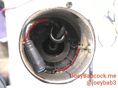
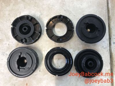
In some cases, pushing the rubber inner part through the plastic retainer ring will make it easier to remove.
Attempt to keep the wires pushed through the rubber part.
Once one of the grommets has been separated/removed, the assembly can be slid out slightly which will make separating the other much easier.
Once both are separated the whole mechanism slides easily out of the pole unless the pole has been damaged or bent.
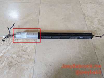
Dissassembling the ESC
The internal battery unplugs fairly easily but the BMS connector may need needle-nose pliers to remove the connector.
3 longer hex screws hold the heat sink in place.
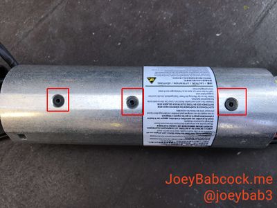
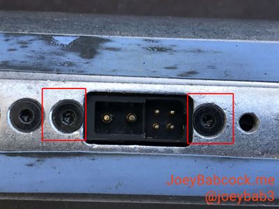
2 shorter hex screws hold the charging port in place.
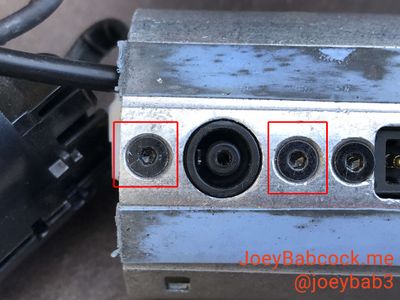
2 shorter hex screws hold the external battery port in place.
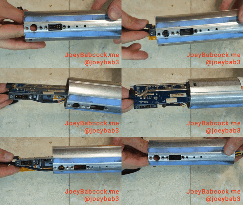
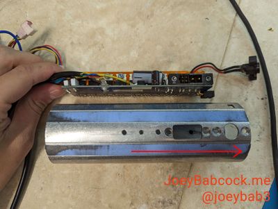
Once all screws have been removed, you can pull the ESC to remove it port end first.
Software
Download STM32 STLink Utility from the ST website.
Scroll down and click "Get Software" and enter your email to receive a download link.
Install it and open it.
Flashing
Connect the STLink to the Master Control Board
Connect pins to 5v/VCC, GND, SWDIO, and SWCLK as shown below.
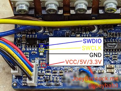
You can solder to these for a better connection or hold DuPont connectors as shown in the image.
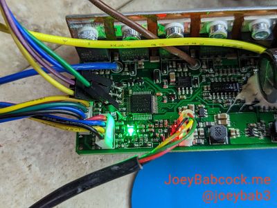
Here I did a poor solder job but it still works.
STM32 STLink Utility
Download the 1.3.9 full dump .bin from ScooterHacking.
You can only flash full dump files or the ESC will not function.
Always check that you are downloading files from trusted sources(aka ScooterHacking) to avoid flashing malicious firmware.
Open STM32 STLink Utility and attempt to connect to the esc with the button shown below.
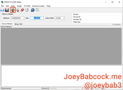
You should be warned that readout protection is enabled if it is connected successfully.
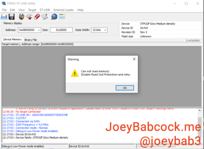
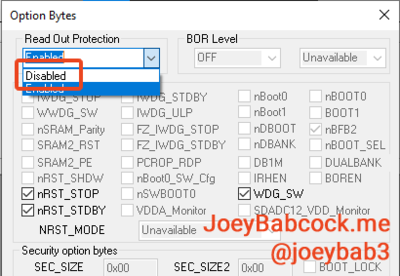
Next, press CTRL + B to open the chip settings.
Select "Disabled" under "Read out protection".
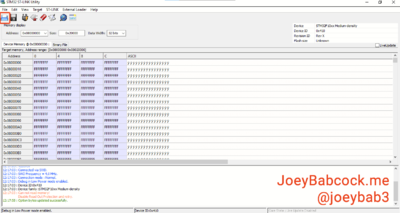
Next, click the open icon on the far right as shown.
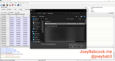
Select the esc_fulldump139.bin file you downloaded earlier.
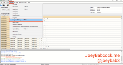
Click Target->Program & Verify or press CTRL + P.
Confirm one last time that the file you are flashing is the full dump and then press "Start".
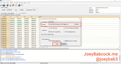
The program will now program the chip with the full dump.
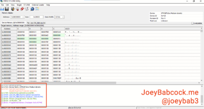
Once it finishes check the console to make sure it was successful.
